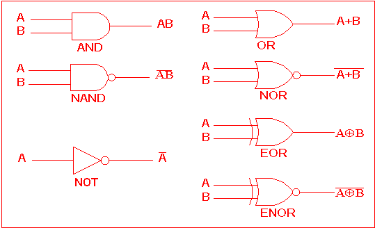
Logic gates Computing:) : chapter 3- logic circuits Digital logic
Logic Gate: Types including Circuit Diagram, Symbols and Uses
Logic equivalent nand xor Circuits logic gates simplify output diagram boolean example questions The following logic gate circuit is equivalent to:\n \n \n \n \n (a
Nand xor logic nor xnor vhdl wiring simulate verify scosche input inputs
Logic gate: types including circuit diagram, symbols and usesLogic gates gate circuits nand basic simply verilog microchip starting diy electrical stack buffers source original components example Logic circuits gates computing types electronic hardwareXor logic gate circuit diagram : 1.
Xor wiringLogic gates and logic circuits Gate diagram logic circuit nand types uses principle working symbolsXor gate logic diagram / xor gate logic diagram.

Gates series logic using two circuit diagram schematic why digital circuitlab created
.
.


Computing:) : Chapter 3- Logic Circuits

logic gates - What is this circuits output and how can I simplify it

The following logic gate circuit is equivalent to:\n \n \n \n \n (A

Logic Gate: Types including Circuit Diagram, Symbols and Uses

digital logic - Why have two NOT gates in series? - Electrical

Xor Logic Gate Circuit Diagram : 1 - The output is 'low' if both the